Sun sensor systems are becoming increasingly important in modern satellites due to growing expectations of better maneuverability, agility and precision control of even very small craft.
This demand for improved performance and control follows a trend we’re seeing in the in-space propulsion sector, which you can read more about on our recent post discussing CubeSat thrusters.
In this article, we take a high-level look at how sun sensors work, what to take into consideration when searching for a sun sensor for your satellite, and give an overview of some of the products currently available on the global marketplace for space.
If you would like to skip the introductory material and go straight to view the available products, please click here, otherwise please read on.

How does a sun sensor work?
Sun sensors in satellite’s navigational systems determine the direction and position of the sun relative to the satellite itself.
They enable attitude determination of satellites by providing two-axis information on the orientation of the satellite using the azimuth and elevation of the sun vector.
To be able to fully ascertain the attitude the third-axis information needs to be realized, which can only happen by adding an additional sensor such as a magnetometer or earth sensor.
Obviously, a sun sensor will not work in the eclipse period in orbit and, if only a very crude identification of the direction of the sun is needed, it can be determined quite easily using the voltage variations in solar panels.
In general, there are three main categories of sun sensor:
- Coarse analog sun sensors: analog sun sensors that measure the current output, which is proportional to the cosine of the angle between the sun and the normal to a photocell.
- Fine analog sun sensors: fine sun sensors that use an aperture to create a sunspot on either a four-quadrant photodiode or a position-sensitive device.
- Digital sun sensors: sensors that operate based on integrating a 2-dimensional light sensor and signal processing, so as to discriminate between direct sunlight and reflected sunlight.
Sun sensors are also used for solar array pointing – orienting photovoltaic energy collection systems (e.g. deployable CubeSat solar panels) for the most effective irradiance – and can also play a role in fail-safe recovery processes and gyroscope updating.
The following paragraphs aim to provide some insights into the differences between these categories of sun sensors and their relative merits.
Coarse analogue sun sensors
This category of sun sensor consists of models with a single photodiode for which the generated current is a measure of the incidence angle. This current varies with the cosine of the incidence angle in a first approximation.
As the derivative of the cosine is 0 at nominal incidence (or zenith) there is a very small measurement signal for angles nearing zenith.
As temperature variations of the diode will lead to signal variations, it is difficult to discriminate between angle and temperature variations at angles close to zenith.
Next to this, radiation degradation will directly influence the calculated angle because the angle is determined on the absolute magnitude of the current generated.
As a result, the zenith accuracy is seldom higher than around 5° while the accuracy can increase to around 3° for angles from 10-50°.
For higher angles, the accuracy again decreases due to tunnelling effects in the cover glass (required to protect the devices against cosmic radiation), changes in the anti-reflex coatings, and variations in the absorption debt.
Next to a low generic accuracy, it should be noted that this type of sun sensor is very sensitive to albedo signals and reflections from satellite parts.
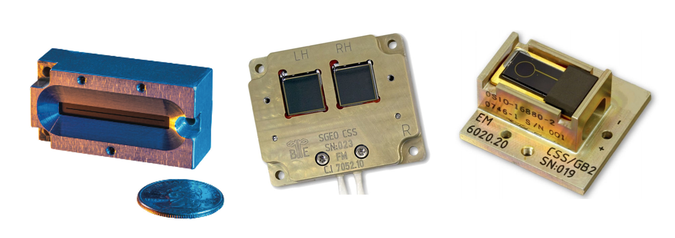
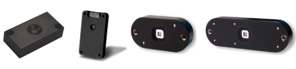
In order to detect the Sun’s attitude in two directions, at least three coarse sun sensors are usually needed, unless a pyramid coarse sun sensor is used.
These sensors (examples of which are shown in above Figure 2) are basically a number of photodiodes mounted on a common structure so as to define the nominal incidence angles for the individual photodiodes.
By combining the signals of a number of diodes the zenith accuracy can be improved over a limited field of view (FOV).
This is mainly due to the fact that the incidence angle is not near normal for the individual diodes (leading to a higher response) and that the ratio of the currents can be used to calculate the angle, removing the need for an accurate temperature compensation.
Even though these sensors are more accurate and can even have internal redundancy, they are not commonly used on small satellites due to their large volume and high costs.
As can be seen in the picture, these sensors are generally equipped with mission-specific baffles to avoid reflections from spacecraft parts having a negative effect on the measurement accuracy.
Fine analog sun sensors
These sensors operate by virtue of the fact that a translucent window provides a light spot which shifts over the sensing element with changing Sun attitude. The most common implementation of which is using a four quadrant photodiode and is shown below.

A membrane is suspended at a known distance above a sensing element (typically a four-quadrant photodiode or position sensitive device (PSD)).
Sunlight, shining through the translucent part, creates a light spot on the sensor. This light spot generates currents in the four independent diodes which can be used to calculate the Sun’s attitude in two directions, if the height of the membrane with respect to the diodes is known.
The formulae that can be used to calculate this attitude are quite simple:

If α is negative: the sun is to the top of the sensor.
If β is negative: the sun is to the right of the sensor (both when viewed from the top side).
NOTE: The illumination given in Figure 3 above is for positive α and positive β.
High quality analog fine sun sensors, such as the Bradford mini-FSS, and the Lens R&D BiSon64-ET and MAUS, can provide an accuracy of better than 1° at zenith and 3° over the entire FOV on the basis of these formulae only, though higher accuracies will always require the use of a number of calibration tables.
Using calibration tables accuracy below 0.5° can be realized, although it should be noted that this is without measurement errors caused by albedo signals, which can reach up to 10° or even 15° depending on orbit height, pointing and cloud cover.
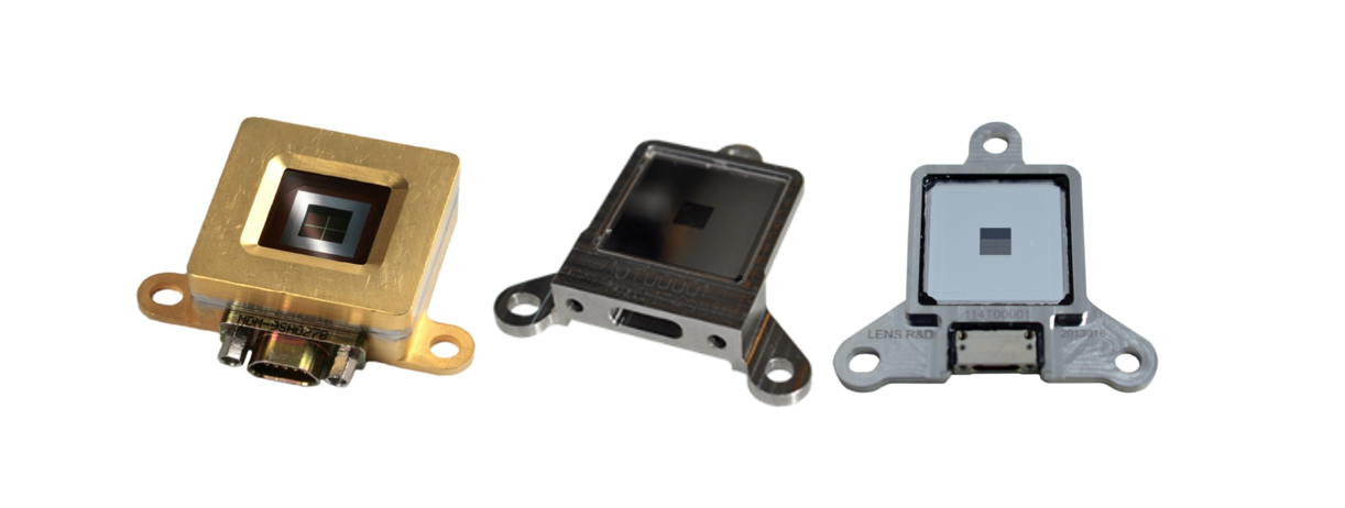
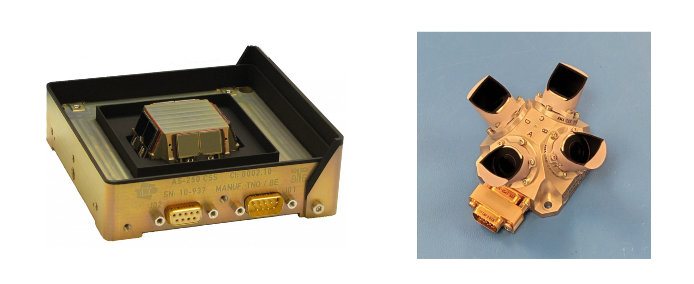
In order to minimize albedo errors stray light baffles can be added as an alternative to creating larger (and more expensive) sensors, for example:
For sensors with this type of accuracy it is important to note that the re-mounting accuracy is part of the pointing budget.
Because of this, all sensors shown in Figure 4 above have a similar mounting strategies that use a ‘highly-toleranced reference hole’; a slotted hole with a high tolerance in one direction combined with an oversized hole that ensures the sensors can be put back in the same orientation with a high degree of confidence.

The reference hole shown on location E5 in combination with the slotted hole detailed in location H7/8 will ensure repeatability of the X- and Y-axis where the flatness of the mounting feed specified in location B9 will guarantee the Z-axis repeatability.
This repeatability is determined by the mechanical tolerances on the mounting holes, the accuracy of the attachment hardware, and the distance between the mounting points.
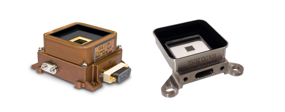
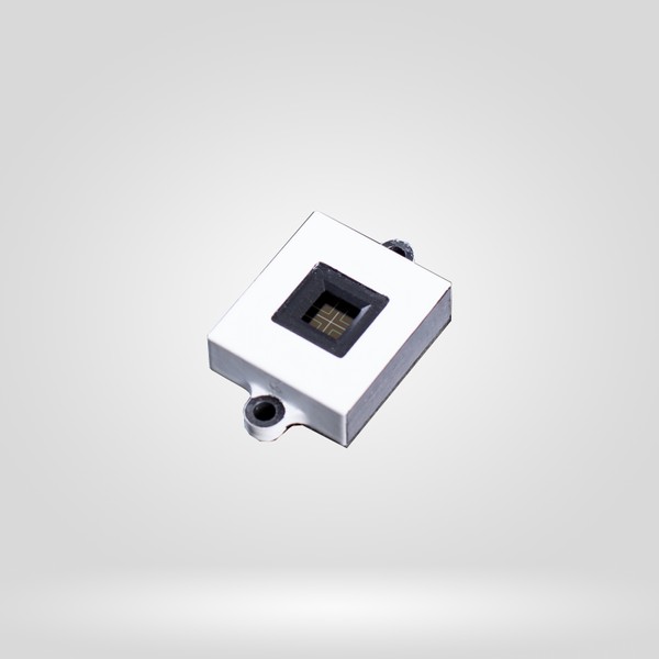
For very small sensors, such as those shown in Figure 7 below, the re-mounting accuracy can easily exceed the specified accuracy due to the close proximity of the mounting holes in combination with a poor mechanical tolerance on the mounting hardware.
One should be aware of these issues when using very small sensors while desiring a high pointing accuracy. In the end the obtainable re-mounting accuracy could mandate a re-calibration after the sensors are mounted to obtain the desired accuracy.
This will obviously complicate the manufacturing process and might well compensate for a slightly more expensive sensor that doesn’t require such a re-calibration.
It should be noted that the re-mounting accuracy is not only an issue to be considered with the smallest sensors. For the Solar MEMS sensors shown below, the mounting holes are specified to be 3.2 mm wide.
The advised mounting hardware is a stainless steel screw according to ISO 4762-2005. The outer diameter of these screws is only 3 mm so there is 0.2 mm of play between the screw and the side of the hole.
The distance between the two holes of the A60 is 4 cm, which means that it is possible to rotate the sensor by as much as 0.4 mm over 4 cm or 0.57°. This is more than the specified 0.3° accuracy of the sensor.

Although these deviations may not be important for the application, it is good to be aware of them, much like the implementation differences that exist.
Solar MEMS Technologies sun sensors for instance use four quadrant photodiodes, but in an immersed configuration as shown in Figure 9.

In an immersed configuration, the cover glass that provides a certain degree of radiation shielding is used as a spacer to hold the membrane through which the sun is shining. This allows for the development of a very compact sensor core and potentially a very small sun sensor.
There are however a number of disadvantages to such an approach, the first of which is that it is very difficult to provide additional radiation shielding without causing multiple reflections.
Another more significant disadvantage is the fact that due to the refraction inside the glass, there is a cross-coupling between the X- and Y-axis which causes the formulae given in Formula 1 above to be rendered invalid.
As a consequence, this type of sensor will always need a calibration table or a more complicated formula. In addition, it will require a temperature compensation if full accuracy is to be obtained because of the refractive index sensitivity to the operating temperature.
Other implementations use a position-sensitive device instead of a four quadrant photodiode. This type of sensor typically uses a much smaller pinhole-like aperture, through which a small sun spot is created on the position-sensitive device; a specific type of silicon detector with four electrodes.
By reading out the sensor, the centroid of this light spot can be determined and thus the direction of the incident sunlight. This is an alternate way to produce an analog sun sensor which is not often chosen because PSD detectors are more prone to radiation degradation, and the smaller pinhole creates less signal thus mandating the availability of proximity electronics.
Despite the smaller pinhole, the sensors have a similar albedo sensitivity to a four quadrant based detector because the relative amount of signal generated is mainly depending on the FOV, accommodation and shielding provisions.
Digital sun sensors
In practice, digital sun sensors are currently a much smaller market segment than analog sensors.
There are various sun sensors on the market which are advertised as digital, but which are actually analog sun sensors with a digital interface.
These sensors will exhibit the same albedo sensitivity and will not allow the ability to exclude certain parts of the FOV from evaluation through digital programming.
Some models feature novel sensing principles with innovative arrangements of linear arrays and a double slits.
Digital sun sensors can also be developed with low mass and small physical footprints, though there can be a potential trade-off with radiation tolerance.

Understanding your requirements
We recommend a simple four-step approach for the preliminary selection of any new piece of hardware or software for a satellite or other space system.
Note that this is just a basic guide based on what we’ve learned helping hundreds of buyers select products within our marketplace and get rapid responses from suppliers.
It is just meant to help engineers make an initial assessment and shouldn’t replace formalised systems engineering approaches such as the INCOSE Model-Based Systems Engineering (MBSE) CubeSat frameworks.
- Specify your currently known mission parameters,
- Record all currently known overall design specifications of the system,
- Consider the range of technology that will be used in the satellite and in ancillary sub-systems, and
- Take into account the key performance criteria of the kind of product you wish to procure.
These criteria are explained in more detail below.
Mission parameters
The first step is to fully understand the currently known mission parameters, including both the critical applications and desirable, but not necessarily essential, objectives.
Typically the more precise mission parameters will only be established later in the process – usually iterated upon in a number of loops by considering the “system of systems.”
But having an idea of what functions your selected technology is likely to need to perform, and on what schedule and duration, will make selecting the most suitable model mch easier.
Also consider the launch stresses, testing processes and regulatory compliance that the product will need to go through in order to make it into orbit, as well as any obsolescence procedures once the mission is complete.
Overall design specifications
Next, keep to hand all currently known design information about the entire unit.
This can include the volume, weight, primary structural material and more basic things such as the location, storage and transport arrangements of the major components.
You will need to make sure that the new piece of technology you choose will be suitable for these parameters.
Full range of technology
Once you are clear on exactly what tasks the new product will need to perform and the design characteristics of the satellite or other unit that it will work within, the next consideration is the full range of technology that will sit alongside the product to make sure that everything is compatible.
You may not yet know the entire range of accompanying technology (and you might need to first choose the product model you are interested in in order to make decisions on other components), but make sure you have access to all available technical specifications of sub-systems and structural components that are most likely to be used, as per the current mission plans.
It is important to understand how different sub-systems and components will interface with each other to create a high-performing satellite.
Balancing the available mass, power and volume budgets is also important, which can only be done with a clear plan of which components will be used.
Also consider how the product will work with the planned or existing ground segment to ensure effective data transfer and communication stability.
Now that you have a clear idea of what sort of product is needed for your mission, system, and existing platform setup, the next step is to compare the commercially-available products that meet these criteria according to the most relevant performance metrics.
Key performance criteria for sun sensors
There are a number of design and performance criteria which dictate the selection of a sun sensor model:
- Field of view (FOV)
- Accuracy
- Environmental characteristics including operating temperature, radiation tolerance limits, and vibration limits
- Available mass and volume budgets
- Costs
- Update rate (for units with integrated electronics)
- Power consumption
- Angular resolution
Sun sensors available on the global market
In the article above we have mentioned a number of sun sensor products in order to demonstrate various core features and differences. Below we have included a more comprehensive list of products available on the global marketplace for space.
These listings will be updated when new products are added to the global marketplace for space at satsearch – so please check back for more or sign up for our mailing list for all the updates.
If you need more information on other smallsat and CubeSat sub-systems we have also put together roundups of several categories such as star trackers, on-board computers, and GPS receivers available on the global market.
Please click on any of the links or images below to find out more about the systems. You can also submit a request for a quote, documentation or further information on each of the products listed or send us a more general query to discuss your specific needs, and we will use our global networks of suppliers to find a system to meet your specifications.
Get more information on all products listed at the click of a button
We can help you access quotes, lead times, or any other information from all of the suppliers listed below (and more) with our simple, free tender system. Just share your details with us and wait for the responses to arrive in your inbox.


The CoSS delivers coarse information about the polar angle of the sun. This information is derived from the fact that the sensor output varies approximately proportional to the Cosine function of the angle of incidence of sunlight.

The design of the CoSS-R exploits the excellent heritage of the dual chip detectors while optimizing the footprint and mass.

An analog sensor based on a quadrant detector that measures the solar aspect angle in two axes. Processing the four quadrant outputs results in the two components of the solar aspect angle. Qualified for LEO with many temperature excursions and for very severe radiation regions (e.g. HEO in Van Allen belts).

Designed to offer rugged, reliable, self-redundant performance to detect sunlight and provide coarse information for a potentially hemispherical FOV. Proven performance with the product continuously in production since 1975 and used in an array of missions.

A similar system to Bradford's Fine Sun Sensor (FSS0 but with a smaller mass and physical footprint. Designed for long-duration LEO missions, a Mini-FSS variant is also available without read-out electronics that is particularly suited for small satellites.
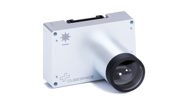
The CubeSpace CubeSense Sun is a CMOS-based fine sun sensor developed for space applications. It consists of a wide field of view, low power consumption, high accuracy, and immunity against albedo effects. The sensor's housing is designed to allow for easy and robust mounting while providing improved EMI mitigation. It is fully calibrated in the company's state-of-the-art dark calibration room.
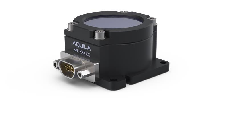
A sun sensor determines a spacecraft’s orientation with respect to the sun. The front surface of the NewSpace Systems (NSS) Aquila-D02 (NFSS-411) sensor is a synthetic sapphire window with a reflective metal coating beneath it. Slits are etched in the metal and sunlight passes through them and through an optical filter onto a sensor.

The Solar MEMS Sun Sensor on a Chip (SSOC) A60 is an analog sun sensor designed for space applications. It is based on MEMS fabrication processes to achieve highly integrated sensing structures for high accurate sun-tracking, positioning systems, and attitude determination. It also includes MEMS technology with flight heritage and electronic components that are space-grade. Every sensor is calibrated and characterized, and a look-up table is provided for its application.

The Solar MEMS Sun Sensor on a Chip (SSOC) D60 is a digital sun sensor designed for space applications. It includes MEMS technology with flight heritage, electronic components that are space-grade, and a microprocessor included has been tested for the space environment and has flight heritage. It is based on MEMS fabrication processes to achieve highly integrated sensing structures for high accurate sun-tracking, positioning systems, and attitude determination.

The Solar MEMS nano Sun Sensor on a Chip (SSOC) D60 is an analog sun sensor designed for Nanosatellites. It is a low-cost and two-axis sun sensor for high accurate sun-tracking, pointing, and attitude determination. The sensor includes MEMS technology with flight heritage and electronic components that are space-grade. More than 1000 flight units have been delivered since 2016, with hundreds of units in orbit.

The Solar MEMS Advanced Coarse Sun Sensor (ACSS) is designed for LEO, MEO, and GEO missions. The ACSS is a device for sun-tracking and attitude determination. ACSS technology acquired flight heritage in 2019 with hundreds of flight units delivered, and its manufacturing process has been developed and industrialized for mass production requested for satellite constellations.

The Solar MEMS nano Sun Sensor on a Chip (SSOC) A60 is an analog sun sensor designed for Nanosatellites. The nanoSSOC-A60 sun sensor is based on MEMS fabrication processes to achieve highly integrated sensing structures. It includes MEMS technology with flight heritage and electronic components that are space-grade. There are hundreds of units in orbit since 2016.
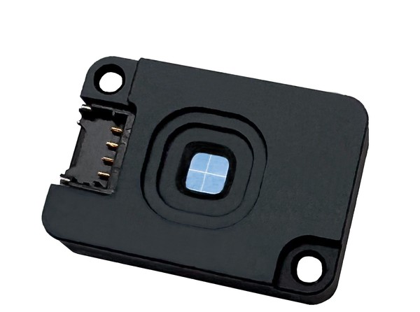
The Tensor Tech FSS-15 is a minimized fine sun sensor with a high cost-performance ratio. It is designed to be mass-produced with stable quality. A microcontroller is embedded in the FSS-15 for tabulated correction using an error table. Therefore, the user can directly access the sun angles from digital interfaces. I2C and UART are two standard communication interfaces. For the error table, every FSS-15 has a unique one, which will be measured before the shipment of the product.
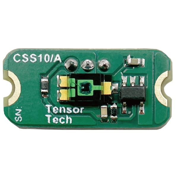
The CSS-10, a coarse sun sensor tailored for spacecraft with minimal pointing demands or those requiring a robust input for sun acquisition algorithms, boasts a simple and durable design. It generates analog signals directly correlated to solar irradiance. The user needs to configure the onboard computer (OBC) or the Attitude Determination and Control System (ADCS) computer's analog-to-digital converter to retrieve data from each CSS-10 sensor.

A 3g sun sensor with outer dimensions of 24.66 x 15.00 x 3.50 mm^3 and sampling power consumption rate of 2.5-4.0 mW. The SS200 has a 110° field of view (FOV) and sampling rate of up to 100 Hz.

The Airbus BASS is a space qualified coarse bi-axis sun sensor designed for low earth orbit (LEO), geostationary earth orbit (GEO), and deep space applications. In the BASS series, the Airbus Defence & Space offers four products - BASS7 GEO, BASS17 LEO, BASS17R LEO/GEO. Some of its other key features include ATOX resistive paint, high strength capability, and thermal coating adapted to the mission.


The Fine Sun Sensor Assembly (FSSA-110) of Berlin Space Technologies hosts up to three analog fine sun sensors. The FSSA can be placed in remote locations of the satellite and reports the sun vector back to the OBC. The FOV of one sensor reaches up to 114°. In order to sense the sun from all directions, 2 units are required. The FSSA-110 is the second generation of our flight-proven FSSA-100 with only minor modifications on it.


The Redwire Fine Pointing Sun Sensor (FPSS) offers 2 measurement axes that enable high-accuracy attitude determination. The unit is radiation hardened to 100 krad (Si) and is AS9100D/ISO 9001 certified. The unit has a typica Field of View (FoV) of ±4.25° x ±4.25° with an accuracy of 15 to 20 arcsec.

The smallest sun sensor in Redwire's portfolio, the MSS provides a cosine output of the sun angle for small satellite applications and can be used for a variety of spacecraft missions requiring sun detection. It has a mass of less than 2g (without wires and glass) and has a minimum field of view of ±85°.

The Redwire Miniature Spinning Sun Sensor (MSSS) is designed to provide sun aspect angle and sun crossing pulses for spinning spacecraft. The sensor has an ±87.5° field of view (from normal to spin axis) and has flown on the ST5, Themis, and MMS satellite clusters.

The Redwire Coarse Sun Sensor (CSS) (Cosine Type) is a small, lightweight sun sensor that offers approximate cosine and conical symmetry Field-Of-View (FOV) capabilities. The single detector system is AS9100D/ISO 9001 certified and radiation-hardened (>100 krad (Si)). Baffles can be provided to restrict the FOV if needed.

The Redwire Coarse Analog Sun Sensor (CASS) contains a 2-segment solar cell for attitude determination. Each cell segment generates a short circuit current (ISC) proportional to illumination intensity. The system has a ±40° field of view, which can be modified to meet specific fov requirements, and 100 krad radiation tolerance.

A TRL 9 sun sensor with a 32° x 32° (each sensor) field of view and ±0.1° accuracy. The DSS32 is typically used for medium-accuracy attitude determination and systems can be configured with one or more optical heads per electronics.

Redwire Fine Sun Sensors (FSS50) are used in attitude control applications where sub-arcminute accuracy and millidegree angular resolution are required. Both single or two-axis configurations. Each sensor can be custom designed to meet specific performance requirements for Field of View (FOV), accuracy, resolution, and other key parameters. The also has a TRL of 9 and is AS9100D/ISO9001 certified.

A is radiation-hardened (to 100 krad (Si)) and AS9100D/ISO 9001 certified sun sensor system with a ±64° fan-shaped field of view for each sensor. Redwire's Spinning Sun Sensors are designed to provide sun aspect angle and sun crossing pulses for spinning spacecraft, in order to determine spin rate and spin axis orientation relative to the sun.

The Redwire Coarse Sun Sensor Pyramid (CSSP) is a 2-axis sensor containing four detectors, used for applications including solar array pointing, sun acquisition, and failsafe recovery. The TRL system has a mass of 0.13 kg and a field of view of > 2π sr. It is AS9100D/ISO9001 certified and has flight heritage an a numnber of missions.

A radiation-hardened, 100 krad (Si), sensor with a field of view of 128° x 128° (each sensor) / 4π sr (achieved with 5 sensors). The system has a transition accuracy of ±0.25° and is AS9100D/ISO9001 certified. The product has a typical power dissipation of 0.4W and has gained flight heritage across a number of missions.
The TY-Space SS-E is a digital Sun Sensor designed for space applications. It consists of two axes of sun vector angle output and has 0.1° accuracy. The product weighs approximately 10 grams and consumes 0.7W of power. It has a field of view of 100° and also has the capability to operate in space for three years.

The Everlight Analog Pyramid Sun Sensor measures satellite attitude and has already been batch produced and deployed to orbit. Three types of sun sensors: Analog Four Quadrants, Mock Pyramid, and Digital, are offered. Each sensor is designed to have high accuracy and sophisticated chipsets. The customers include the Chinese Academy of Science Shanghai Innovation Academy for Microsatellites, CGSTL, and ASES Shanghai.
The Everlight Analog Four Quadrants sun sensor measures satellite attitude and has already been batch produced and deployed to orbit. Three types of sun sensors: Analog Four Quadrants, Mock Pyramid, and Digital, are offered. Each sensor is designed to have high accuracy and sophisticated chipsets. The customers include the Chinese Academy of Science Shanghai Innovation Academy for Microsatellites, CGSTL, and ASES Shanghai.
If you would like our assistance in finding a suitable sun sensor for your needs from our extensive network, please fill out a request for information or proposal, and we’ll get back to you as soon as we can.
Sun sensing technology is a large and active area of the market and the listings above are not exhaustive – we are actively working on updating this information and will share any updates via our email list below and on social media.
Noticed that your product isn’t included in this article? Send us an email today today we’d be happy to work with you to showcase it to the satsearch community!
Related technologies and further reading
At the links below you can find a range of satsearch articles that will be useful for learning more about this topic, or that feature other categories of technologies which you may need to consider in your mission.
- Attitude sensors
- Satellite electrical power systems (EPS) on the global market
- CubeSat thrusters and in-space propulsion
- Software-defined radios (SDRs) for space
- On-board computers (OBCs) for space
- Components of satellites
- Optical payloads for space
- Payload processors for satellites
- A brief introduction to the space supply chain
- Reaction wheels for space on the global market
- Earth sensors
- Space grade solar cells
- Solar Array Drive Assemblies (SADAs)