This article discusses how to choose a satellite on-board computer (OBC), exploring the different criteria that engineers typically consider when assessing products available on the market. It was developed in collaboration with STM, a participant in the satsearch membership program.
OBCs provide processing capabilities as part of a satellite’s avionic sub-system and run the on-board software that controls many aspects of the satellite’s operation.
As such an integral part of any satellite it is important that developers select an OBC that meets the needs of their system and intended applications.
This guide provides an overview of 11 important criteria to consider when selecting an OBC for your satellite.
1. Orbit
One of the most important criteria in the selection of the OBC is to determine the orbit in which the satellite will operate. There are three main satellite operational orbits known as LEO, MEO, GEO:
LEO – Low Satellite Orbit is the closest orbit to Earth. Satellites in this orbit are situated between 500 – 1,000 miles altitude. Signals leaving the satellite can reach ground stations in around 0.05 seconds from this orbit. This orbit is preferred for minimum signal delay applications.
MEO – Minimum Earth Orbit satellites mainly operate at around 8,000 miles altitude. Signal delay on this orbit is around 0.1 seconds. MEO is mainly selected for high-speed data and high bandwidth signal applications and many telecommunications and military satellites mainly operate in this orbit.
GEO – Geosynchronous Equatorial Orbit satellites mainly operate at 22,000 miles altitude. This operational altitude enables coverage of the entire planet. Satellite TV is a good example of an application operating in this orbit.
The distance of the satellite from the earth (orbit) affects the rotation speed of the satellite, its coverage area, the amount of radiation it is exposed to, and consequently, the satellite’s service lifetime.
For example, a telecommunications satellite is expected to rotate at the same speed as the earth, meaning the satellite operates in geostationary orbit. These satellites have a high coverage area, are planned to operate for a long time, and have high radiation resistance. But this also makes the systems more expensive.
If we consider another example, Earth Observation (EO) or Automatic Identification System (AIS) satellites will operate in LEO orbit. Such systems can make more than 10 turns around the earth in a day, have narrow coverage (for high resolution), short-term operation, lower radiation resistance, and are usually cheaper to build and run.
2. Mission duration
Like the rest of the components of a satellite, OBCs also have an operating lifetime in space. This lifetime is mainly dependent on the radiation level of the space environment. OBCs’ electronic components are key factors to estimate the mission duration.
For short duration missions COTS components can be used, but for longer duration missions, radiation-hardened components need to be involved in order to make satellite lifetimes longer.
Alongside high-quality electronic components the reliable and robust design of an OBC is also very important in considering mission lifetime.
3. Power requirements
Power consumption is critical as the generated power in solar cells is very limited. Power consumption can be different for various satellite operations such as imaging, compressing and transmitting processes. During operations OBCs should ideally consume little power while still operating effectively.
Field-programmable gate arrays (FPGAs) used in OBCs are important components to consider when calculating power consumption.
FPGA technologies differ widely in their power consumption characteristics. To be on the safe side it is important to know that both flash and anti-fuse FPGAs are true live-atpower-up technologies which do not exhibit large inrush current spikes at power-up.
Moreover, because Flash FPGA technologies are non-volatile they do not suffer from the high configuration current needed during each power cycle. The power consumption of other components can be considered to a lesser extent than that of the processor, but some attention should be paid to power consumption when selecting them.
4. Weight and dimension restrictions
OBC dimensions and weight must be compatible with the satellite. For instance, nanosatellite platform weights are typically a maximum of 10 kg. An OBC that will sit on a stack (which can be a PC104 connection) is expected to have a maximum weight of between 100 – 200 g and should be compatible with this structure in terms of width, length, and height.
For microsatellites an OBC used in a 100 kg satellite does not have a definite standard regarding the size, but it is expected to have its own case, be as lightweight as possible, and have its dimensions and connector placement to support the satellite harness.
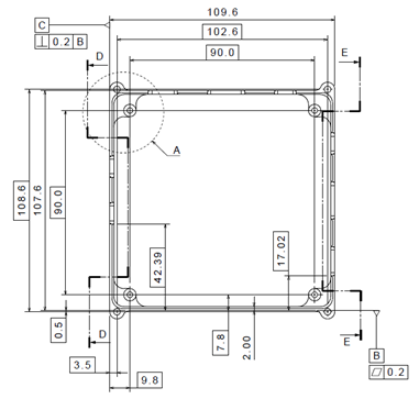
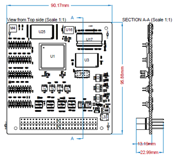
Sample OBC size and weight:
- Mass – 100 g
- Length – 95 mm
- Width – 90 mm
- Height – 18 mm
- Mass – 280 g
- Length – 130 mm
- Width – 126 mm
- Height – 18 mm
5. Computing power
Every mission plan requires an understanding of similar resources such as power, memory, weight, size etc. One of the most important resources in space missions is time. If the satellite is not geostationary the ground station will be waiting for the satellite to orbit the earth so it can transfer the precious data.
Also, the gap for transferring data is usually very short (often a narrow window of 3-10 minutes) so the satellite data transfer system needs to be fast enough to operate in this window, as does the ground station. This requires fast processing and computing power.
Missions mainly consist of a single main task and a number of side tasks. To achieve these tasks on time and transfer data to the ground in the data transfer gap, satellites require sufficient computing power.
Therefore, the main criteria to consider in determining the required computing power are the tasks the satellite should run the before data transfer gap, and then the work required to transfer those task results to the ground station during the gap.
In addition, the hardware should be able to support fast processors as these use clock signals generated by the hardware. For example, if a 4 GHz processor is using 2 GHz data bus to communicate, communication speed will be 2 GHz. This means that 4 GHz of processor speed will be excessive and will unnecessarily drain power.
6. Interface requirements
As the OBC will be required to interact with various sub-systems it is very important that it has a sufficient number of communication ports and protocols.
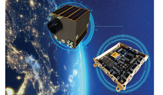
For example, the STM NANOSATPRO supports the most commonly used interfaces such as UART, RS485, CAN, SPI, I2C and GPIO. In addition to these, the MICROSATPRO also has the Spacewire interface.
Employing a CAN bus communications network in satellites enables much lower power consumption and reduces the amount of wiring and connectors required vs. the conventional MIL-STD-1553 and RS-485 point-to-point interface solutions.
With CAN, several nodes are attached to a single bus which significantly reduces system and cable costs.
Besides the variety of communication protocols, the weight and miniaturization of physical connectors are also important. The OBC should be as small and light as possible to fit into mass and size limits.
Lightweight composites, rugged plastics, and electromagnetic interference shielding are some of the many component design elements that can contribute to weight saving. These criteria were taken into consideration in the data and power connectors of the MICROSATPRO for example.
7. Fault tolerance
COTS components are typically more sensitive to radiation compared with custom (radiation-hardened) components. Therefore it is important to guarantee the reliability of the system by adopting fault-tolerant design approaches.
Low-cost COTS components allow satellite developers to exploit the radiation hardening technique through hardware redundancy; to make the components suitable for space use. Although it doesn’t promise 100% reliability, fault-tolerant design approaches can improve the overall reliability of the system to a great extent.
A ’Watchdog’ may be the last line of defense against radiation. As radiation can affect electrons in both dynamic and static memory, it can cause infinite loops and cycles, or malfunctions in the system. These software malfunctions can be repaired with a soft restart provided by a watchdog.

A watchdog is a timer that counts to zero from a set time (for this reason it is also known as WatchDogTimer or WDT). It needs to be reset (known as “kicking WDT”) before it reaches zero, otherwise it creates an interrupt that causes a soft restart. In this way, if software becomes trapped in an infinite loop or malfunction, the WDT will not be reset in the normal manner, which will trigger a soft restart of the software.
The STM MICROSATPRO is tolerant to Single Event Effects (SEE) in logic and data storage with enhanced error detection and correction. SEE protection is provided through the use of a Fault Tolerant (FT-LEON3) processor core, Triple Modular Redundancy (TMR) in FPGA, Error Detection and Correction (EDAC) in memory units, watchdog on software, and Latch-up Current Limiter (LCL) in power units.
8. Static and dynamic memory size
Similar to computing power, satellites require memory for mission tasks. Dynamic memory size mostly depends on the software to be loaded on the satellite.
Such software should be designed around the mission objectives, so the more complex and sophisticated the satellite, the more it requires effective dynamic memory.
Software size also affects static memory, but the main determining factor for static memory is data collected in each orbit.
For example, if a satellite’s main task is recording high-resolution video footage, it should be storing the footage in static memory as dynamic memory could be erased in the case of a power interruption or a restart. This way task results can be saved and accessed in the short data transfer gap.
For safety reasons there also can be another static memory that holds a copy of the satellite software in case of malfunction in the main static memory. This also helps with updating satellite software as there will be a static main code stored in a different memory which can be booted in the case of an unseen bug or malfunction.
In aerospace applications dynamic memory allocation should be avoided as it may cause overflows and malfunctions in the system. Software usage of RAM and static memory should be determined as realistically as possible. In addition, processor architecture and software optimization should be considered here to determine memory usage.
9. Compliance testing
Ensuring OBCs are rigorously tested for the space environment after the design and production phase is completed is an important selection criterion. Environmental tests aim to show the resistance of satellite mission computers to environmental conditions in space and their compliance with customer requests.
The purpose of these tests is to create the most realistic environmental conditions encountered by the satellite during the process from launch to orbit, and to ensure that no operational problems arise when OBCs are exposed to these conditions. The main forms of test are:
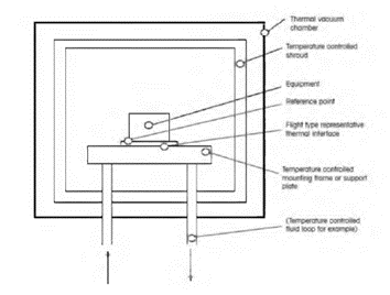
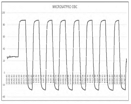
a) TVAC (Thermal Vacuum)
The durability of the OBC has to be proven within the scope of ECSS-E-10-03A standards by simulating the low pressure, heat fluxes, and other environmental aspects that mimic space in a Thermal Vacuum Chamber.
b) Vibration
The effect of the mechanical loads generated by the action of the launcher on the satellite mission computer are observed in the 3 main axes with vibration tests. Vibration tests are completed in accordance with the ECSS-E-10-03A test standard.
c) Shock
The simulation of the shock loads that occur at certain stages, such as the separation of the OBC from the launcher, are carried out in shock tests, according to the ECSS-E-10-03A standard.
d) Radiation
Radiation effects of high-energy particles in space can have a very detrimental effect on components of sensitive OBCs, as explained above.
The threat to the computer varies greatly depending on the satellite’s orbits. In high-penetration gamma ray testing, resistance up to 30 krad values with Cobalt-60 irradiation is observed in the OBCs designed by STM.
The tests were completed within the scope of ECSS-Q-HB-60-02A standards. The customer can choose an OBC according to their budget and requirements according to the processor with high or low radiation resistance of the satellite mission computer.
e) EMI/EMC
Testing electromagnetic interactions before OBCs get to the launch stage is very important.
In order to verify that each piece of equipment in the OBC works in harmony in terms of electromagnetic interactions, this form of testing is carried out within the scope of compliancy regulation MIL-STD-461G Test standards, in a fully non-reflective area.
EMI/EMC tests are performed as in the list below, in accordance with the relevant MIL-STD-461G test standard:
- CE102 – Conducted emissions, power leads, 10 kHz to 10 MHz
- CS101 – Conducted susceptibility, power leads, 30 Hz to 150 kHz
- CS114 – Conducted susceptibility, Bulk Cable Injection
- CS115 – Conducted susceptibility, bulk cable injection, impulse excitation
- CS116 – Conducted susceptibility, damped sinusoidal transients, cables and power leads, 10 kHz to 100 MHz
- RE102 – Radiated emissions, electric field, 10 kHz to 18 GHz
- RS103 – Radiated susceptibility, electric field, 2 MHz to 40 GHz
10. Legacy (flight heritage)
Generally, a certain spaceflight legacy is expected to be requested by the customer to ensure reliability of satellites and their OBCs.
This is mainly because it is desirable to ensure reliability without facing the cost of redesigns.
11. Sensor requirements
Sensors can be divided into three branches:
- Mission critical sensors
- System health sensors
- Navigation and positioning sensors
Mission critical sensors, as the name suggests, depend on the mission objective and tasks, which can be widely varied as they are often for military or research purposes (e.g. EM detectors, spectrum analyzers, temperature sensors, vibration sensors, cameras etc.).
System health sensors collect information on the current status of satellite systems, monitoring critical indicators such as voltage, current, temperature etc.
Some loopback tests included in the system are also stored with these sensor data as system health. These data provide very important information about the current satellite status which is used, for example, in the case of a malfunction.
Navigation and positioning sensors are primarily required in missions where there is a need to rotate or move the satellite to another orbit.
Such sensing systems may include, for example, a gyroscope to provide the current direction of the satellite, and a GPS receiver to provide current position.
Understanding exactly what sensors and sensing configurations are required in a mission or service is important for choosing the right satellite OBC.
Conclusion: understanding how to choose a satellite on-board computer
Selection of the best OBC for a satellite is one of the most important stages in its development, as it is central to the coordination and operation of all the different sub-systems and mission critical functions.
While decisions may be driven in part by price, location, and lead times, the 11 criteria detailed above should hopefully help you make more informed choices to shorten development and testing cycles – ultimately leading to a better satellite.
Find out more about STM and its portfolio of OBCs on the satsearch platform – you can also contact the company here if you have any further questions on OBC selection for your mission, constellation or service.